Antenna building
Just as a camera needs a lens, a radio receiver needs an antenna. You can easily build your own Yagi antenna to listen to meteors with the use of an RTL-SDR dongle.
The design of a Uda-Yagi antenna is characterized by three components: the actual active part (the dipole) and two parasitic elements; the reflector at the back and a director at the front. The element lengths and their mutual distances listen closely, because the two parasitic elements have to resonate in phase with the dipole. The mutual distances determine the wave travel time and the element lengths determine the resonance frequency. Signals from other directions run more or less out of phase and are therefore less amplified or even attenuated. In this way the received signal is bundled along a certain direction and, in the case of a 3-element antenna, amplified by 5 dB (3x). This principle was discovered in 1926 by the Japanese Uda and Yagi, the latter of which published an English article about the antenna. Directional antennas operating according to this principle are therefore usually called Yagi antennas.
Self-construction
You can buy ready-made 3-element 144 MHz (2m) antennas from about € 70 to € 80. An antenna for the 6m band is even more expensive due to longer element lengths. Such a Yagi antenna, however, is also very easy to make with materials from the local hardware store. The dimensions remain manageable and due to the relatively low frequency the tolerances are large enough for a nearly 100% success guarantee. For the GRAVES radar and BRAMS meteor beacons you will find two building descriptions below that have been optimized for radio frequencies of 143 MHz and 49 MHz by radio amateur Simon Bijlsma (PA7SB).
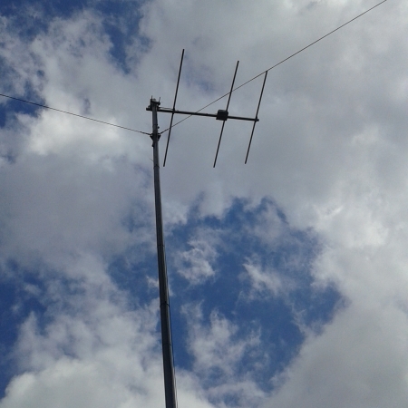
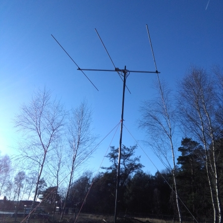
Photos: CAMRAS (Simon Bijlsma) Self-built 3-element Yagi antennas for meteor observations. With the building descriptions on this page you can make one of these antennas. Left the antenna optimized for GRAVES (143 MHz) and right for BRAMS (49 MHz). Both Yagi antennas are constructed after the DK7ZB design and adapted to the dedicated beacon frequencies.
Tools required
To build the directional antenna according to the building description below, you need the following tools:
Pipe cutter and or hacksaw
Drill and 4, 6, 9 and 13 mm metal drills
Soldering iron and soldering tin
Tape measure
Screwdriver
Spanners
Cutter
Yagi antenna for GRAVES (143 MHz)
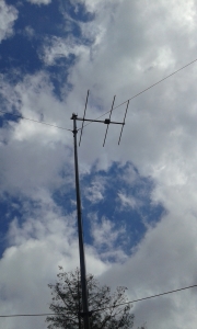
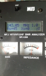
Photos: CAMRAS (Simon Bijlsma)
This is what you are going to make: a 3-element Yagi antenna for GRAVES.
Components:
1 round aluminium tube 2 m long, diameter 13 mm
1 round aluminium tube 1 m long, diameter 13 mm
1 square aluminium profile 1 m long, diameter 20 mm
1 antenna mast clamp 20 × 20 mm
2 plastic element holders (among others ‘Tino’s Funkshop’) *
1 aluminium corner profile 20/40 x 75 mm
1 BNC chassis part, alternatively N chassis part
1 plastic junction box
1 PVC tube diameter 15 mm, 50 mm
1 PVC tube diameter 15 mm, 70 mm
1 coaxial cable RG 58 approx. 50 cm (other types of thin 50 Ohm coaxial cable possible)
3 bolts, rings and nuts 4 mm, 40 mm
4 bolts, rings and nuts 4 mm, 30 mm
2 small welding eyes 4 mm
1 choke ‘pig nose’ or resistance 1k Ohm
Overview of dimensions:
Reflector: position 0 mm, length 1060 mm
Dipole: position 480 mm, length 1000 mm (2 x 495 mm, 10 mm spacing)
Director: position 760 mm, length 890 mm
BUILDING MANUAL IN 10 STEPS
STEP 1 – Construction starts with the customization of the elements with the aid of a pipe cutter or hacksaw. Then you begin by sawing the support boom at the desired length. At the indicated positions you drill 4 mm holes in the support boom where later the elements and the dipole connection box are mounted.
STEP 2 – In order to be able to mount the antenna both in horizontal and vertical polarization, it is recommended to make the support boom approximately 12 cm longer. With a total length of 88 cm, the antenna clamp can be placed behind the reflector (see photo below). If you mount the clamp directly behind the dipole you can omit that extra 12 cm and the whole is more in balance. But then you can only use the antenna for horizontal polarization, otherwise the (metal) antenna mast will disturb the radiation pattern of the antenna.
STEP 3 – Saw or cut in half the aluminium tube for the middle element(the dipole). At 5 mm from the ends you drill a hole through which the bolts can penetrate and later fix both the elements and RG 58 coaxial cable. Insert the dipole halves into a 70 mm long PVC tube so that the ends leave a gap of 1 cm between the two dipole parts. In the PVC tube you drill (measured from one side) at the positions 25 and 45 mm also two holes for the bolts through the tube and the aluminium tube parts (see photo below).
STEP 4 – Drill the 13 mm holes for the elements on both sides in the cable box and a 9 mm hole for the BNC chassis part. Drill also a 4 mm hole in the middle on the bottom to secure the cable box to the boom with a bolt.
STEP 5 – For the fastening of the cable box on the other end, drill a hole of 4 mm at the bottom of the aluminium corner profile through which a bolt goes to fasten it to the support boom. This is also the earthing point with which the dipole is connected to the support boom. Drill a 9 mm hole on the other side of the corner profile, this serves for the BNC chassis part.
STEP 6 – Drill two 6 mm holes at both ends of the 50 mm long PVC tube. Pass the RG 58 coax cable through the first opening. Wind a coil of six windings around the tube and insert the last piece of cable through the second 6 mm hole. The coil of the RG 58 coaxial cable around a PVC tube serves to suppress so-called common mode currents (see photo below). An alternative is a ferrite ring or clamp that is suitable for VHF. Without these filters, the antenna also works, but there is a chance that interference from the environment, via the outer casing of the coaxial cable, will reach the antenna.

Photos: CAMRAS (Simon Bijlsma) Yagi antenna for the GRAVES meteor beacon. The inside of the junction box with the dipole is enlarged on the right. See the text for the detailed description.
STEP 7 – Assemble the bolts through the 70 mm PVC tube and the two dipole halves, and mount it with a bit of dexterity inside the junction box. Put the welding eyes on which you soldered the RG 58 coax cable and the ‘pig nose’ on the bolts and tighten the nuts. The so-called ‘pig nose’ serves to prevent that static discharges can damage the RTL-SDR dongle. Of course you can directly solder it with the RG 58 coaxial cable in the same welding eyes. The extra eyes in the photo have been used because the ‘pig nose’ has been added afterwards and in order to not having to loosen the already soldered cable. The other end of the coax cable is soldered to the BNC chassis part. The BNC chassis part is grounded to the support boom and the mast via the aluminium angle piece (see photo above).
STEP 8 – Drill holes for the attachment bolts of the element holders right in the middle of the tubes for the reflector and the director. In this way you can later attach the reflector and the director to the boom.
STEP 9 – You are now almost ready to use the antenna. Connect a coaxial cable to the BNC chassis part of the junction box that already has a BNC plug. A suitable adapter must be fitted to the other end of the cable, for connection to the RTL-SDR dongle, for example from BNC to MCX or SMA. This depends on your type of dongle.
STEP 10 – Finally, screw the antenna clamp onto the boom and attach the entire Yagi antenna to an antenna mast or tripod stand if required; you are now ready to receive your first meteor reflections.
* The element holders can also be made by yourself, for example according to this construction method . An alternative mounting method is to pierce the bearing boom with the pipe diameter of the element. The element can then be fixed by screwing a screw through it. The elements can therefore also be made of 8 mm or 10 mm tube, although the mechanical strength is somewhat less with a smaller diameter. In the case of antennas that are often moved, a thicker tube is therefore firmer and it bends less quickly. It does not matter for the operation. Another alternative is to 3D print the element holders. Various designs for element holders for Yagi antennas can be downloaded for free via the Thingiverse website. But beware, different diameters and / or mounting methods have consequences for the critical length of the elements. Thinner elements must be slightly longer than the thicker ones, and insulated elements are shorter than non-insulated. For more explanation, we refer you to the DK7ZB website or the Rothammel antenna book.
Yagi antenna for BRAMS (49 MHz)
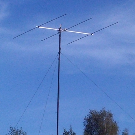
Photo: CAMRAS (Simon Bijlsma)
Just as you can make a directional antenna for the GRAVES radar, it is also possible to build an antenna for the dedicated 49 MHz BRAMS meteor beacons. Follow the same 10 steps in the building description, but use the materials below to make the antenna for meteor detections on the wavelength of BRAMS.
Components:
6 round aluminium tube 2 m long diameter 13 mm
1 round aluminium tube 1 m long diameter 10 mm for connection of the 13 mm element halves.
1 square aluminium profile 2 m long diameter 20 mm
1 antenna mast clamp 20 × 20 mm
2 plastic element holders (among others ‘Antennas-Amplifiers’) *
1 aluminium corner profile 20/40/75 mm
1 SO-239 chassis part, alternatively BNC or N chassis part
1 plastic connection box
1 PVC tube diameter 15 mm 50 mm
1 PVC tube diameter 15 mm 70 mm
1 coaxial cable 75 Ohm eg Satellite cable or RG 59 approx. 250 cm (2x 1/4 Lambda 28/50 Ohm balun **)
3 bolts, washers and nuts 4 mm 40 mm
3 bolts, washers and nuts 4 mm 30 mm
2 small welding eyes 4 mm
1 choke ‘pig nose’ or resistance 1k Ohm
Overview of dimensions
Reflector: position 0 mm, length 3020 mm
Dipole: position 920 mm, length 2845 mm (2 x 1415 mm, 15 mm gap)
Director: position 1850 mm, length 2660 mm
*see footnote to the building description above.
** see the DK7ZB website(link below) for more information on the 28/50 Ohm balun. Pay attention to the correct velocity factor (V), this is cable type dependent and in this case 0.82. The propagation speed of the wave through the satellite cable is about 82% of the speed of light (c), therefore the physical cable length must be shorter than the calculated wavelength. In our case (c / f x 0.25 x V) 300 / 49.97 x 0.25 x 0.82 = 123 cm
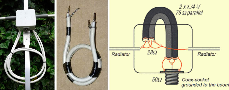
Photo: CAMRAS (Simon Bijlsma) 2nd photo and illustration Martin Steyer DK7ZB. For the BRAMS antenna it is necessary to make a 2x 1/4 Lambda 28/50 Ohm balun. On the left you see the end result atached to the cable box, in the middle the intermediate result, on the right the soldering diagram.
Cabling
Whichever antenna you choose, it is important to use low-loss coaxial cable and preferably cables that are not too long, because otherwise too much signal is lost. For lengths exceeding 10 m it is not recommended to use the type RG 58 coax cable. Expensive cable types such as EcoFlex, Aircom +, H2000 are not necessarily needed; the cheaper Aircell 7 cable is very useful. However, if longer lengths of coax are required, such as at the setup at the Dwingeloo Telescope (130 m), it is necessary to use a ‘Low Noise Amplifier’ (LNA). This is an amplifier with a low inherent noise and a large amplification. This LNA amplification compensates for the cable loss and therefore the weaker reflections are also clearly audible. Without the LNA the signals are weakened by the cable loss by about 10 times (this is called a cable attenuation of 10 dB). Because of this effect, the meteor set-up becomes very ‘deaf’ for the reflections of meteors.
Placement of the antenna
Finally, it is important to mention that the placement of the antenna is important. The careful selection of the best location of the receiving antenna requires some experience. You may be able to seek advice from a local radio amateur (if you know someone, of course), because they usually have experience with setting up antennas and minimizing interference. If desired, you can walk around with a portable receiver (AM modulation) to find the spot with the minimum noise and interference. A signal finder can also help to find sources of interference, which for a few euros is sold as a construction package by Scouting. Sources of interference are such as plasma TVs, LED lighting, switching power supplies, PLC(internet over powerlines) so called ‘optimizers’ and inverters of solar panels. This kind of interference sources can spoil the fun during radio observing or in some cases make it impossible to receive reflections from meteors at all. If you live in an urban environment we advise you to listen to the GRAVES radar instead of the BRAMS beacons because of aforementioned reason. Probably the 2m antenna is also small enough to mount it on a balcony if you do not have a garden.
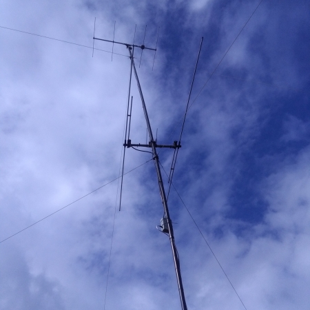
Photo: CAMRAS (Simon Bijlsma) Yagi antenna for the webSDR of CAMRAS. The Yagi antenna (on top of the mast) is slightly tilted so that it looks up at an angle of 10 to 15 degrees.
For fixed setups, experience shows that the best result is achieved by placing the antenna as high as possible, at least 3 to 4 meters high. The received signal strength is greater then because there are fewer obstacles in view of the antenna. It also reduces the chance of local interference being received due to the greater distance to disturbing devices. Also the alignment of the antenna has a positive effect for the observation. The antenna is mounted slightly tilted, so that the antenna looks up at an angle of about 10 to 15 degrees. The beam within which the antenna is sensitive is then already more in the direction of the area in which the reflections take place and it has the additional advantage that slightly less ground noise and interference is received. The antenna can be mounted both vertically and horizontally polarized. Depending on the local conditions, one radio set-up works just a bit better than the other. In most cases, the vertical arrangement is somewhat more noisy, partly because most of the interference sources are vertically polarized. On the other hand, I have the impression that vertically the reflections are usually somewhat stronger, which probably has to do with the influence of the earth’s magnetic field. Experimentally, you can test what gives you the best signal-to-noise ratio (SNR) locally, because that is more important for detections of meteors than the absolute strength of the signal.
More information on antenna construction
- Alois Krischke DJ0TR – ‘Karl Rothammel: Antenna book, English edition’
- Martin Steyer DK7ZB
- Derek Hilleard G4CQM
- Webshop antenna-parts
- Paul Hyde(G4CSD) article (BBC SkyAtNight): ‘How to use radio signals to catch meteors’
Text contribution: Simon Bijlsma (PA7SB), radio amateur, amateur astronomer and volunteer at CAMRAS, the C.A. Muller Radio Astronomy Station.
