To easily observe the Sun and Jupiter, NASA has a project called ‘Radio JOVE’. For that project, NASA sells a kit for a receiver and the antennas. The aim of the project is that, for example, schools can easily conduct radio astronomy themselves.
The antenna for the Sun is a single tuned half wave dipole. For the observation of Jupiter and the moon Io, a single dipole is not sensitive enough, therefore a directional antenna is recommended. This is easily achieved with a combined arrangement in which two dipole antennas are coupled together with two coax cables that are electrically exactly a wavelength long. This is called a phased array. By alternately connecting an extra 135 degree(0,375 λ) or 90 degree(0,25 λ) phase delay cable, the antennas are electrically made adjustable in both the direction and height. The physical mast height is also adjusted if necessary, so that the efficiency of the antenna more than doubles with respect to a single dipole. Although some coupling loss (3 to 4dB) should be taken into account, the extra forward gain and improved front to back ratio reduces the unwanted background noise significantly compared to a single dipole. For the Jupiter observations the phased array antenna is therefore recommended.
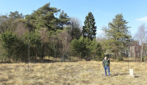
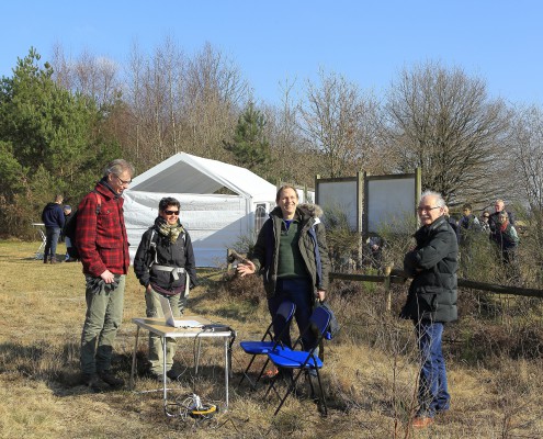
Simon Bijlsma at the Jupiter antenna setup Photo: CAMRAS (Harry Keizer)
Radio JOVE at CAMRAS
In 2016, CAMRAS volunteers Erik van der Toom and Simon Bijlsma came up with the idea that it would be interesting to build a similar Radio JOVE setup. During the stargazing days, we set up optical viewers to watch Jupiter. It would then be very interesting to be able to listen to the radio signals at the same time. This allows us to give the public a look into the fascinating world of (radio) astronomy. It is a nice demonstration of what is possible with very simple means. The antennas are made of standard materials from the hardware store, the receiver is a so-called RTL-SDR dongle with a so-called up-converter to make the low short-wave frequencies audible. An arbitrary AM shortwave receiver whose AGC (automatic gain control) can be switched off also suffices.
Antenna setup
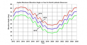
For the NASA project, building kits are sold in which the components are present to build a receiver and the wiring for the dipole antennas including the coax cables. This kit is very useful for those who do not have as much experience with building antennas, because all supplies (excluding the masts) are delivered. However, the concept is so low-threshold that it can easily be copied with items from the local hardware store and we have done that at CAMRAS. The masts that support the antennas in our case consist of glass fiber parts of 1.30 meters long, which are put together to the desired height. The army used these masts for camouflage nets. In principle every random mast of sufficient height can be used. NASA recommends to hang the antennas at 4.57 meters (15 ft) height to have an elevation angle of about 40 degrees that is favorable to our latitude. Our setup is 4.90 meters high because three of the four parts of the mast have penetrated each other 10 cm.
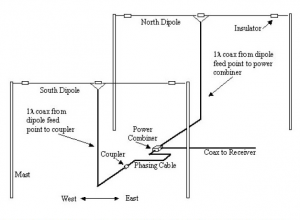
antennas with phase delay cable.
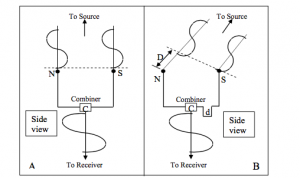
working principle of a phased array

illustrations: NASA (Radio JOVE RJ1.2 Antenna Kit Assembly Manual 2012)
When can Jupiter be heard
The declination of Jupiter varies from 23.5 degrees south to 23.5 degrees north over a 12-year cycle, with one period of observers in the northern hemisphere having an advantage and the other period observers in the southern hemisphere. The distance between the Earth and Jupiter also varies with time because the orbits of both planets are elliptical. Fortunately, in 2016 the declination of Jupiter is just favorable enough for our hemisphere. In addition, Jupiter is closest to the earth on 8 March. If the ionosphere is quiet at night, so that the signals of around 20 MHz are not reflected back into space, then it should be possible to receive Jupiter with our antennas.
the variation in the declination of Jupiter
The signals are subdivided into so-called: ‘S-Bursts’ and ‘L-Bursts’. The S stands for ‘short’ and L stands for ‘long’. The first sound like a crack, the latter can be compared to the sound of the surf.
Results
On Saturday, March 12, 2016 during the national stargazing days, we have put up and tested the above configuration. During the day the ionosphere was active as expected and radio amateurs from around the world could be received around 21 MHz. From eight o’clock in the evening the first ‘S Bursts’ signals from Jupiter were received, while the planet was still low in the sky and also a little way out of the preferred direction of the antenna, which mainly was bearing south. Later in the evening, Jupiter was higher in the sky and also turned more to the south and thus full in the beam of the antenna. In retrospect, we had better set up the antenna a bit more towards the east to have better reception results earlier in the evening when there were more visitors. The reason we did not do that was that the 25m Radio telescope was in the way and I personally did not expect to be able to hear anything at the lower elevations.
Nevertheless, it was also audible earlier in the evening and even when the signal was stronger later on, the public still had to be told what was to be heard. The signals were not very strong and the amplitude also did not differ so that people who are not so familiar with listening on the shortwave might only hear ‘noise’ in almost all cases. That is why I regularly demonstrated the difference between the noise at the 20.1 MHz frequency and the much flatter and softer noise at 30 MHz where Jupiter could not be heard. This could convince most, as it seemed in any case. From the observation I have made several audio recordings that the program GQRX stores in wav format.
The next time it would be possible to make it even clearer and better graphically by using the SpectrumLab program on a Windows laptop. The GQRX program I used does have a ‘waterfall display’ but a bit less advanced than that of SpectrumLab.
Update
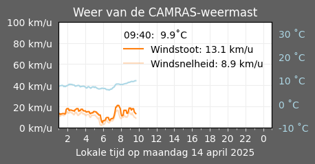
Recently (October 2024) we have added a 15m ‘radio JOVE’ receiver to the webSDR for the decametric radio emissions of the planet Jupiter in conjunction with one of its moons Io. However most of the time, when the ionosphere is to dense, only terrestrial signals can be heard like the 15m amateur band. The antenna is a double dipole phased array bearing South at 4,9m AGL.
Simon demonstrates the Jupiter synchrotron and Meteor scatter setup Photo: CAMRAS (Harry Keizer)
Text contribution: Simon Bijlsma (PA7SB), radio amateur, amateur astronomer and volunteer at CAMRAS, the C.A. Muller Radio Astronomy Station.